Drive demonstrator with a new driving profile
In order to show visitors to our stand and other events something interesting from our portfolio, we have adapted our previous drive demonstrator with a new driving profile and more functionalities. This extended driving profile demonstrator shows an example of a setup with all components in active operation, so that visitors can get a good idea of the inner workings of electric drive technology for a generic application.
Above all, the demonstrator is to be adapted with a functionally extended driving profile in order to make even more functionalities explainable. An engine control system is to be integrated for this purpose.
Comparison of the driving profiles
Previous driving profile
The previous demonstrator only has a simple driving profile:
- Motor on
- Motor rotates at a rotation speed generated by the voltage and only in one direction
- Motor off
Future driving profile
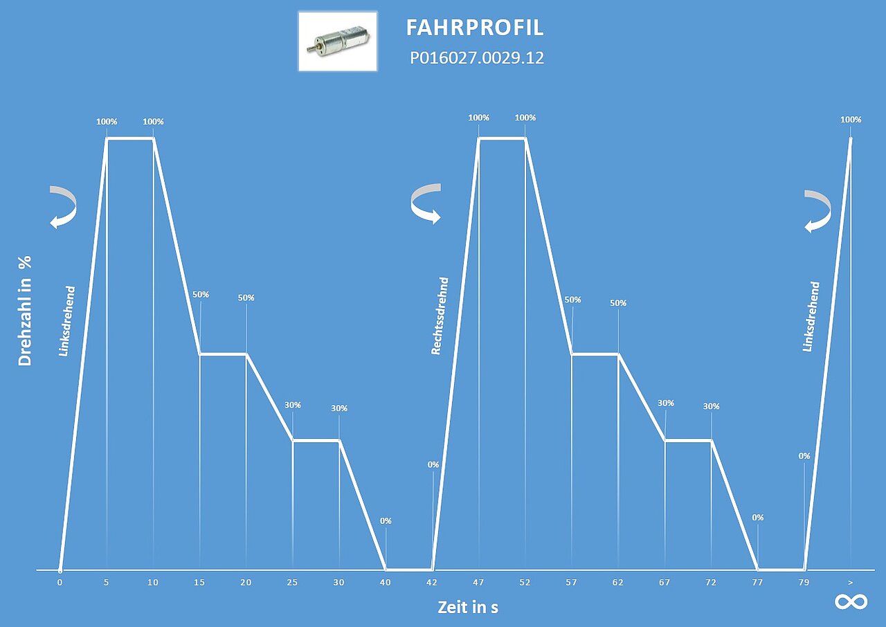
In order to be able to show more functions, we have decided to adapt it to run several different driving profiles:
- Motor counterclockwise
- Ramp from 0% rotation speed to 100% rotation speed
- Motor turns to 100% for 5 seconds
- Motor brakes to 50%
- Motor turns to 50% for 5 seconds
- Motor brakes to 30%
- Motor turns to 30% for 5 seconds
- Motor brakes to 0%
- Motor remains at 0% for 2 seconds
- Reversal of the direction of rotation of the motor to clockwise rotation
- Ramp from 0% rotation speed to 100% rotation speed
- Motor turns to 100% for 5 seconds
- Motor brakes to 50%
- Motor turns to 50% for 5 seconds
- Motor brakes to 30%
- Motor turns to 30% for 5 seconds
- Motor brakes to 0%
- Motor remains at 0% for 2 seconds
- Restart at point 1
After a defined pause, the program starts again. The arrangement, duration and pauses of the individual segments of this still simple but illustrative driving profile can be further expanded so that it can become very comprehensive in real applications.
Driving profile with motor control
Both the hardware and the logic need to be changed for this somewhat more complex driving profile.
Hardware
- Previously:
The motor used so far is too slow in rotation speed and too weak for slow driving. At low rotation speeds, the shaft jerked. - Future:
In addition to the logic, the control system also requires hardware, which all together should remain economical.
Software
- Previously:
No software required. - Future:
The control logic requires software support, which must be created specifically for this purpose.
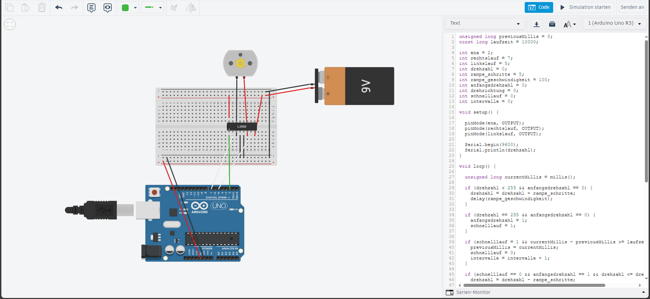
Simulation of the circuit
In order to keep the development time for this demonstrator short, the structure was created in a simulation program. The circuit was built in the simulation program. This approach quickly made it clear which electronic components were required, and the software code could be generated directly in connection. A lot of trial and error was required to achieve our goal with the controller, as there are various approaches and options for creating the code. Each of these options has advantages and disadvantages. Even with a supposedly "simple motor controller", there are always unexpected challenges that can be solved with creativity and experience. In the end, the code was created, which excellently depicts all functions in the simulation and brings us closer to our goal.
Simulation versus testing in reality
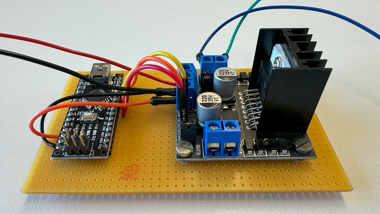
To test the previous simulation in reality, the required hardware was procured and the circuit built. The software code was optimized in several loops to meet the requirements. A simple circuit board was produced for the driving profile demonstrator, which both fits into the existing housing and can be assembled quickly and economically.
Choosing the optimum electric motor
Which motor will best meet the new requirements of the adapted driving profile?
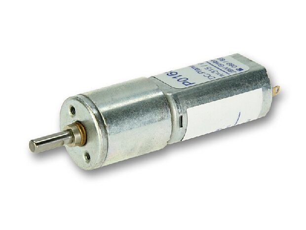
After several tests with different motor types, the decision was clearly made in favor of the powerful DC planetary gear motor P016027.0029.12, which delivers excellent rated power in all required load conditions. The armature of the worm geared motor should be able to be demonstrated both at high rotation speed and at very low speed. These are major challenges for a motor because they are competing objectives. High torques at low rotation speeds are also possible for smaller gears. As the requirement for rotation speed at the same torque increases, the motor must become stronger and thus geometrically larger. However, as the installation space in this demonstrator is limited, it is important to find the best compromise. This was found with the planetary gear motor from the P016027 series and a reduction ratio of 29:1.
In addition, a physical relationship is of great benefit: As the rotation speed is proportional to the applied voltage, a 12 Voltage motor can be used, which already had a lower rotation speed when driven by the 11.1 Voltage battery. This can be reduced to a standstill with PWM control of the electronics - without losing the necessary torque. This enables smooth driving cycles of a speed ramp from standstill to maximum rotation speed.
Motor control compact in a pot
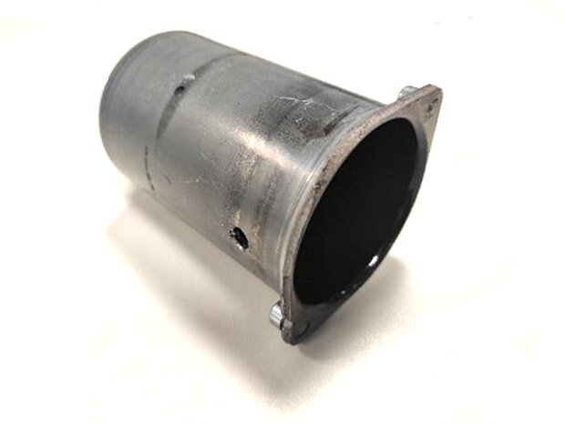
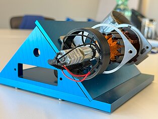
As with the previous demonstrator, the individual components of the motor control unit should not be openly visible. The driving motor and its motor mount were already concealed in the demonstrator pot. The power supply and cabling were hidden in the demonstrator holder. And it was to be designed in exactly the same way again, but now there was only a very small installation space left for the many additional components.
Battery with suitable power supply
A suitable power supply had to be procured to ensure continuous operation throughout the day, depending on the event. To do this, the energy consumption of the individual components had to be determined and the capacity of the suitable battery had to be designed for a minimum duration of 8 hours.
Mechanical processing in the prototype workshop
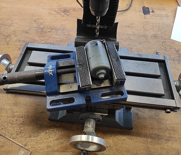
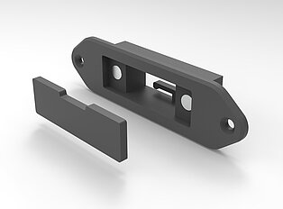
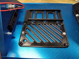
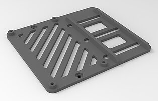
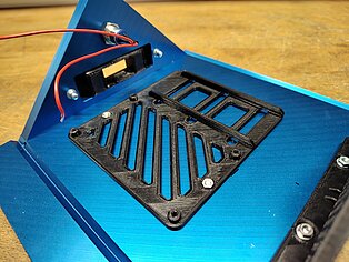
We adapted the motor pot, the housing and the brackets to the new requirements. We enlarged the hole in the wall of the pot for cable routing on the underside, as the wiring had increased significantly in diameter.
The inside of the motor pot was painted black to better accentuate the blue LED lights and give the whole thing a rounded look. The pot holder and the housing were also re-drilled.
Concentricity of the shaft connections
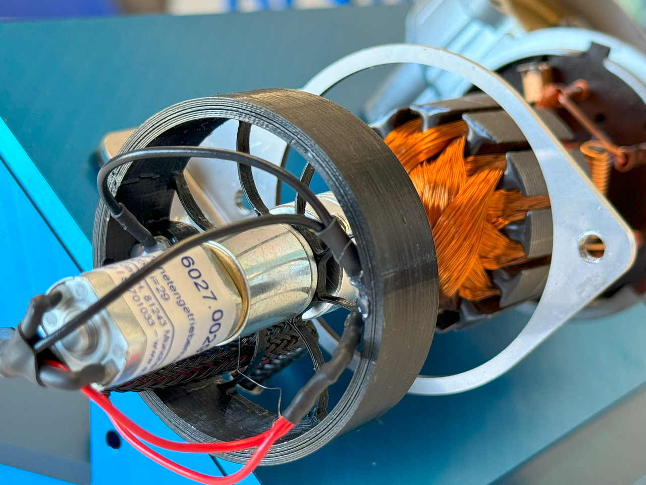
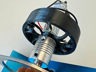
Concentricity plays an important role in the connection between the driving shaft and the driven shaft. This is particularly relevant for the service life, as the load on the bearings in gears and mountings is incomparably higher when axial forces act cyclically. These loads increase further if vibrations are added, which can also have a negative effect on other machine parts. The higher the rotation speed, the faster an application is confronted with problems. For the demonstrator, the choice fell on a shaft coupling with clamping screws and a special mounting for the motor. This mount for the planetary gear motor P016027.0029.12 developed in the 3D system allows the motor to absorb axial forces and thus compensate for the misalignment of the shafts. This significantly increases the service life. Everything is matched to the torque to be transmitted. In addition, this special motor mount can accommodate the LEDs for the lighting effects. JBW produced these parts on its own 3D printer, which is ideal for a prototype such as this demonstrator.
What use cases does this demonstrator reflect?
In fact, this demonstrator stands for all shafts to be driven, which should be able to do more than ON / OFF, but which does not require a control loop, but works in actuating mode. For this current setup, this means that the sensors would have to be intercepted by a higher-level process control system. Of course, signals from various sensors could also be evaluated and processed in this prototype demonstrator. If necessary, this will then be mapped in another drive demonstrator.
Applications for this drive profile demonstrator
- Format adjustment on cutting units, material feeders, logistics systems such as order picking systems or in machine tools
- Flap adjustment
- Pump shaft
- Dosing device
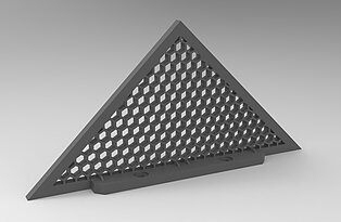
Further construction details in pictures
Meet JBW!
Check our news to see if you can meet us at a trade fair such as SPS in Nuremberg or SPS Italia in Parma in the near future. Bring the specifics of your application with you. We will find the right solution together.
Alternatively, simply give us a call and we can meet online or in person to discuss your application in detail.
Please let us know how such exemplary applications help you and which other applications for electric drive technology you would like to see explained on our website. You can either contact us by phone or email or you can also post your comments on our JBW company profile on Google*).
*) You must be logged into Google to use the QR code or the link to go directly to the input field in our company profile on Google. We welcome every friendly review, but we also understand anyone who does not want to comment publicly.


