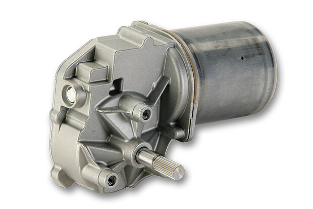
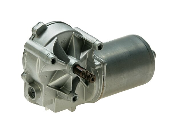
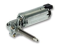
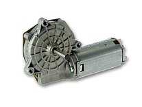
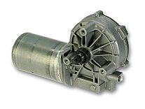
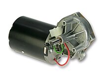
A DC motor with wor m gearbox is suitable for high torques and low speeds. Although a worm geared motor can withstand high loads, it remains quiet in operation. It is also ideal where a certain degree of self-locking is required but additional brakes are not required. The often decisive factor: A worm gear motor is both powerful and cost-effective. Let's talk about your application if you are initially thinking of a more expensive BLDC motor. By comparing the requirements and costs in detail, we have already amazed many a customer.
Worm Gear Motors
Series SWMV motor-type 403763

| Motor type | 403763 |
|---|---|
| Type | DC |
| Rated voltage (VDC) | 24 |
| Rated power (W) | 200 |
| No load speed (Upm) | 250 |
| Rated speed (Upm) | 212 |
| Rated Torque (Nm) | 5 |
| Stall torque (Nm) | 40 |
| Gearbox position | L |
| Gear wheel material | Plastic |
| Direction | L/R |
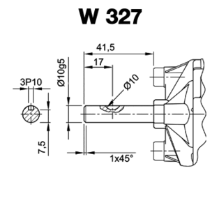
| Shaft 1 | W953 |
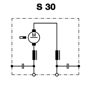
| Circuit diagram | S166 |
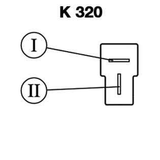
| Connection | K968 |


Technical description
Crankcase: rolled, corrosion-resistant
Magnet field: permanent magnet
Mounting armature, A-position: ball-bearing
Mounting armature, B-position: cup-bearing
Gear type: worm gear
Gear box: zinc diecasting
Gear wheel: plastic or fabric-base plastics or bronze
Lubrication: grease, permanent lubrication
Interface mechanical: output shaft
Interface electrical: connector or litz wire with connector or tin-plated litz wire
Notices
Modification of the output shaft with feather or woodruff key, plains or additional internal threat.
Mounting on demand of hall-IC, encoder, tacho sensor or brakes.
If required, we mount and deliver motors with any add-on parts, e.g. rubber-metal buffer, clutch or any brackets.
The right worm gear motor in just three steps

You need the right worm geared motor for your application. Your must-have criteria: Quiet and with a certain degree of self-locking.

We will show you the ideal worm geared motor to match your specification. You will receive all detailed drawings and characteristic curves. On request, we can also test it on our drive test bench.
Fields of application for the worm gear motor
Agricultural machinery, gate drives, machine tools, special vehicle construction, household appliances, lifting systems, lift systems, positioning systems such as an X-ray table arch, vending machine systems, sorting systems, safety bars, etc.
Automation in industry and the home
What all these applications have in common is that there are frequent load changes and good adjustment is required for positioning. As a worm geared motor has significantly less gear backlash due to its direct transmission between the worm shaft and worm wheel and at the same time generates friction, it is self-locking by design. It can hold positions that have been approached, which in some applications saves the installation of additional brakes. Of course, a brake is still installed for safety reasons, e.g. for chain hoists, but it may be smaller in size.
And even more plus points
A worm geared motor is compact because it offers a high transmission ratio in a small housing. As it is always angled at 90 degrees (right or left), it is often more space-saving in length than other DC motors. For larger loads in the 5-10 Nm range, it is even smaller than a planetary geared motor and also significantly more cost-effective. Our main supplier, manufacturer of most of our worm geared motors, ensures the perfect match between motor and gearbox so that these DC motors can demonstrably withstand the loads mentioned.
Here you will find the right worm geared motor in various series to make your selection easier. The grouping into series indicates, for example, the respective design and identical gearbox parts.
Technical description
- Motor housing: galvanised or painted steel
- Magnets: Sintered iron
- Armature shaft bearings: Sintered bronze bushes / ball bearings
- Gearbox housing: Plastic or aluminium-zinc injection moulding
- Worm: Steel
- Worm wheel: Plastic, steel or bronze
Catalog with the series of our worm gear motors
Always have the catalogue for our worm geared motor series to hand. On just a few pages, you will find a good overview of the technical data for the motor types of the various worm geared motor series. Physical specifications and performance data as well as information on the interfaces.
Application-specific additional equipment
A DC geared motor alone often does not cover all requirements. Our engineering team will work with you to consider what else is needed or which variant we can customise for you if your standard supplier has delivery problems or has discontinued old series. We receive such enquiries frequently and we almost always find the ideal solution.
- If you need an adaptation in the mechanical structure, we can replace the hollow shafts, for example.
- If you need an motor control unit for flow and return, then we have the right control unit in our range or we can even have it manufactured to specification if the range of functions is unusual.
- Do you need housings for temperature sensors or thermal switches? We can produce them to size using our own 3D printing system.
Either way, we provide you with fully assembled drive systems for installation. And even if it's just a matter of soldering on a cable - thanks to our reliable distribution logistics, we deliver the electrical drive technology to you ready for installation and on time.

Technical advice
Misel Korcanin
misel.korcanin@elektromotore.eu
"Tricky technical questions about a worm gear motor? I'm always particularly looking forward to that because I'm very familiar with it. Just tell me what you need!”
Characteristic curves for each motor type
We provide you with the motor characteristics with our standard load profile or with individual requirements, as you need for your application.
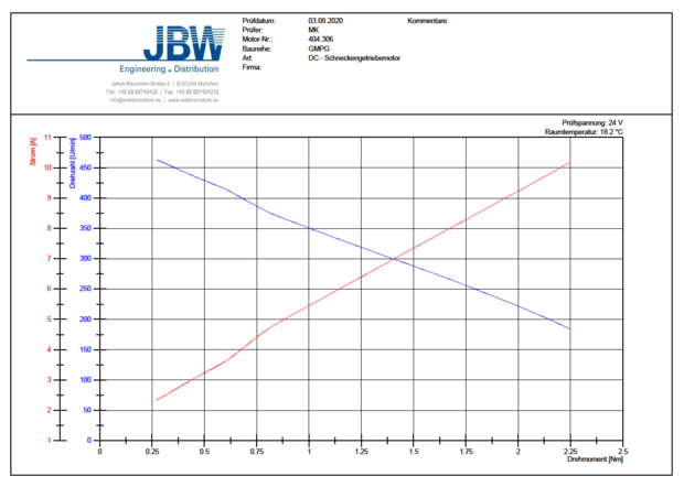
The motor characteristics show the torque on the X-axis, the right-hand Y-axis shows the speed (blue) and the left-hand Y-axis shows the current consumption (red). On the JBW drive test bench, we use the brake to increase the load so that the motor becomes slower and slower (the blue speed line decreases). As it continues to rotate, it consumes more current (the red line increases). The characteristic curves therefore reveal the behaviour of the respective motor type.
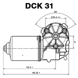
DCK 31 motor series
Worm shaft and worm wheel
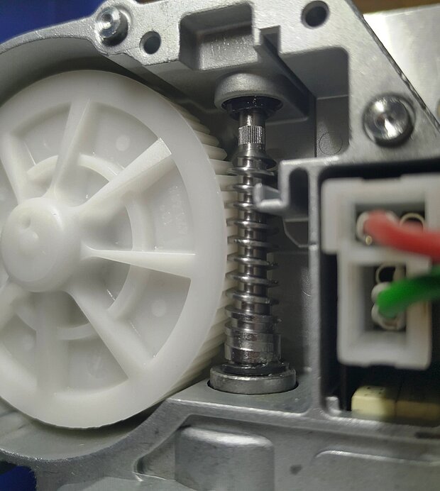
Most applications are driven by a powerful, high-precision worm gear that combines a screw drive with a gear drive. The steel worm shaft with its attached worm, a linear screw thread, engages with several teeth simultaneously in the gaps of the worm wheel, a metal or plastic gear wheel. The axes of the two are usually offset by 90 degrees. However, this gearbox also reliably compensates for slight axial misalignments between the input and output. Both directions of rotation are possible via left- or right-hand worm threads. The worm shaft and worm wheel are in permanent contact during the sliding rotations. This is why the worm gearbox is the quietest , which also generates a high power transmission in a small space with the toothed drive and ensures a high load capacity .
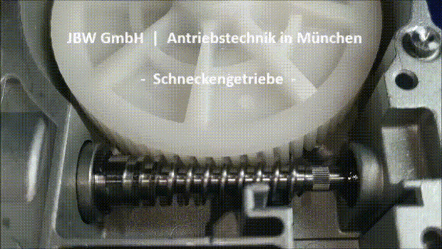
Here in the picture you can see the worm geared motor 404.864of the DCK 31 series. It has an armature speed of approx. 5000 rpm and the worm shaft rotates identically. Due to the gear ratio of 1:69, the motor shaft reaches a speed of around 70 rpm. The transmission ratio is calculated from the number of teeth on the worm wheel and the number of gears on the worm shaft.
Reduced sliding friction
Our manufacturer and supplier of complete worm geared motors, the Japanese group of companies NIDECskilfully copes with the increased demands on the production process in terms of precision and surface finish, as these two criteria together reduce friction. Because of the sliding friction, the worm and worm wheel are also made of different materials: The worm, which is subject to greater wear, is made of hardened steel, for example, while the worm wheel is often made of softer materials such as brass, bronze or a self-lubricating plastic. During continuous operation, a suitable lubricant ensures that the heat generated by the low efficiency at high gear ratios is dissipated.
14.02.2020 | New DCK motor housing
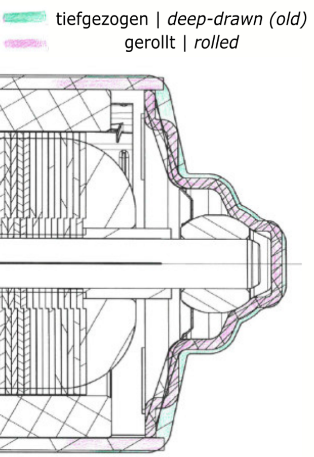
Due to a change of supplier at the manufacturer of the DCK worm gearbox motors from calendar week 07/2020, the motor housings will be produced rolled instead of deep-drawn. This only slightly changes the outer contour of the housing as shown in the picture. ONLY the housing will change, i.e. all other components as well as all processes at the manufacturer will remain unchanged. In future, there will therefore only be a single housing for all DCK motors. The change has been tested by the motor manufacturer and the functionality remains the same. The drawings will be made available to us by the manufacturer after the update.

Worm gear motor | Your questions and answers
This catalog provides an overview of the motor types in the various worm gear motor series. Each series is presented on one page with technical data such as physical specifications, performance criteria, connections etc. as well as a photo and drawing.
This depends on the particular geared motor, but is usually feasible.
This depends on the gear ratio used in the worm gear stage. A worm gearbox is not always self-locking, as it depends on the load case and transmission ratio.
The worm gear motor is considered to be very robust due to its mechanically simple design with its direct transmission. However, even this motor cannot last forever under constant overload. There are various ways of prolonging its life, e.g. with special greases depending on the application.
Please send us an e-mail to info@elektromotore.eu with your contact details and the motor for which you need the CAD model. We will then be happy to send you the data models or contact you for clarifications.
Interesting facts from the press
Directly cooled electric motor made of plastic
Everything should not only become smaller and smaller, but also lighter. This applies to drive technology components. The Fraunhofer Gesellschaft is researching future alternatives in the context of the electric car. It is exciting to see what fibre-reinforced plastics and a new type of cooling concept can achieve.

